 The Accumetrics' Battery Powered Telemetry System
Model AT‑5000 EasyApp provides easy, dependable wireless measurements, including torque measurements, strain measurements, and more, from a rotating shaft. Measure torque live in real-time with this battery-powered, digital telemetry system. Featuring
a low mounting profile and low power consumption, the system requires no shaft modifications and is fastened to the shaft using a single, sturdy aramid fiber strap. AT‑5000 EasyApp is an ideal non-contact data transmission solution for applications
requiring easy installation and dependable data retrieval, even in high RPM applications.
The Accumetrics' Battery Powered Telemetry System
Model AT‑5000 EasyApp provides easy, dependable wireless measurements, including torque measurements, strain measurements, and more, from a rotating shaft. Measure torque live in real-time with this battery-powered, digital telemetry system. Featuring
a low mounting profile and low power consumption, the system requires no shaft modifications and is fastened to the shaft using a single, sturdy aramid fiber strap. AT‑5000 EasyApp is an ideal non-contact data transmission solution for applications
requiring easy installation and dependable data retrieval, even in high RPM applications.
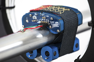
The Battery Powered Telemetry System Model AT-5000 EasyApp utilizes a small battery powered transmitter mounted using an aramid fiber strap to directly measure, digitize, and transmit true torque data from rotating half-shafts, driveshafts, and rotors
of all sizes and speeds. The system is also used for temperature, voltage, and acceleration sensing.
The AT-5000 EasyApp uses a long-life lithium battery to excite a strain gage and to power the AT-5000 telemetry electronics on the rotating
shaft. The small signal resulting from torque applied to the shaft is amplified, anti-alias filtered, and digitized (typically at 11,718 samples per second). The digital data is reliably RF transmitted off the rotating shaft to a nearby pickup coil,
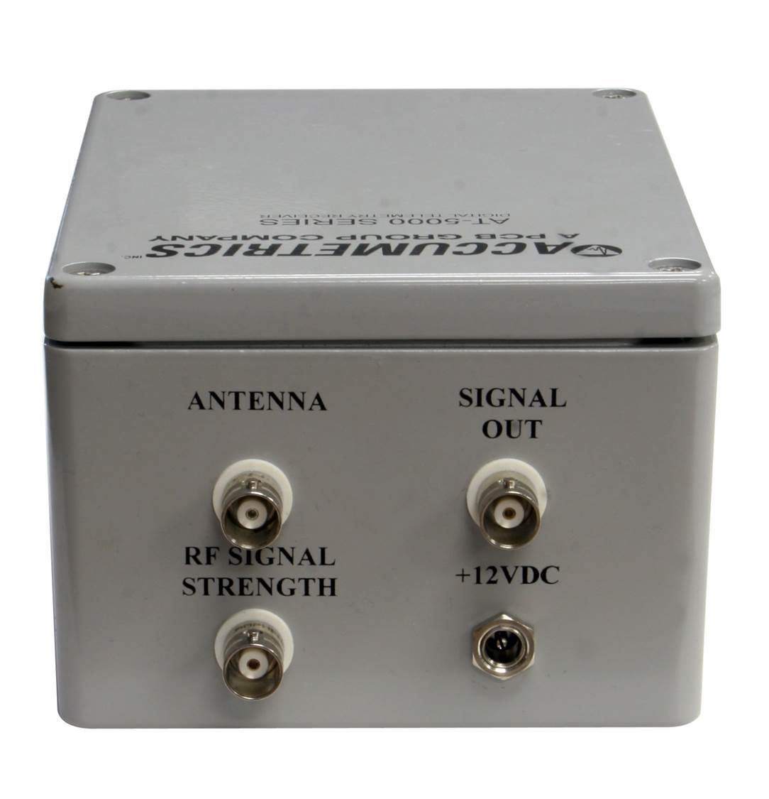
which is connected to a receiver. The receiver converts the digital data to an analog voltage output (adjustable from 0 ± 1.0 to ± 10 volts). This DC to 1 kHz (or optionally higher) bandwidth voltage output can be fed directly to a data
acquisition system, FFT analyzer, or an oscilloscope.
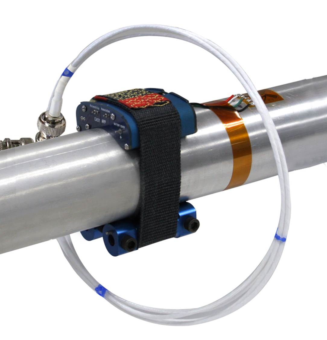 | 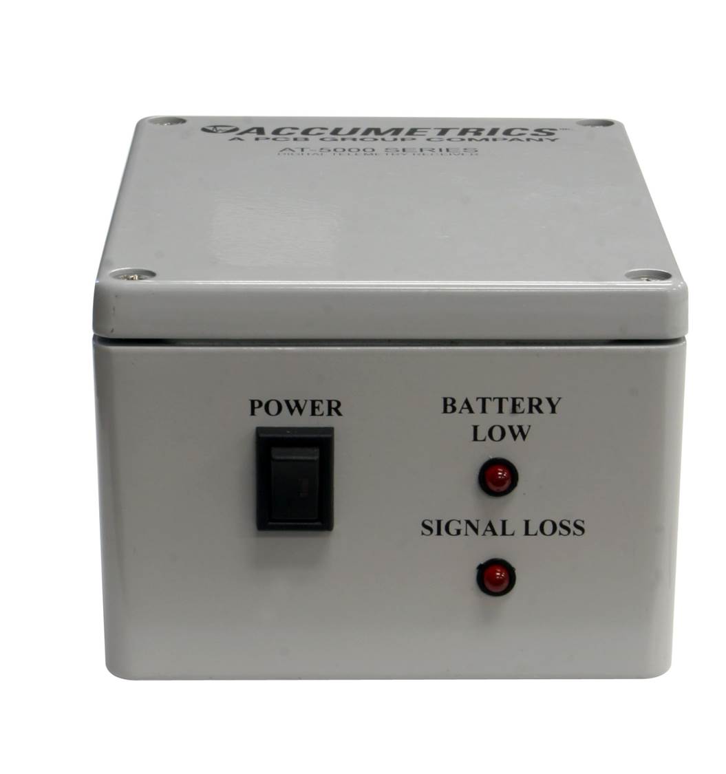 |  |
| AT-5000 Transmitter and P/U coil | AT-5000 Receiver | AT-5000 Receiver |
| AT-5000 Transmitter for > 0.9"/22.86 mm Diameters | AT-5000 Transmitter for > 2.0"/50.8 mm Diameters | AT-5000 Transmitter for > 8.0"/203.2 mm Diameters |
| SPECIFICATIONS | |
|---|---|
| Transmitter Modules - Sampling Rate / Typical Bandwidth | |
| Channel A Transmitter | 7812 samples per second; DC to 1.2 kHz frequency response; 4 MHz transmitter |
| Channel B Transmitter | 11,718 samples per second; DC to 1.2 kHz frequency response (DC to 5 kHz available); 6 MHz transmitter frequency. (Channel A and B units can be co-located for 2-channel use.) |
| Transmitter Module [1] | |
| Non-linearity | <0.1% of full scale (typical) |
| Digital Resolution | 12-bit (0.025% of full scale) |
| Gain Drift | 100 PPM/°C typical, exclusive of external gain resistor |
| Offset Drift | 0.7 μV/°C typical (0 85 °C) |
| Bandwidth | DC to 1.2 kHz (up to 5 kHz bandwidth available; AC coupling also available) |
| Power | Typically <4 mA current draw from 3.6 V battery, excluding sensor excitation |
| Temperature | -40 to 185 °F (-40 to 85 °C) High Temperature option is available |
| Battery | |
| Battery Voltage | 3.6 V open circuit; 3.4 V loaded. Low battery indication is transmitted to receiver at approximately 2.7 V. |
| Bridge Excitation | 2/3 length AA. Single use Lithium battery. Note: Non-rechargeable batteries. Do not store or use in applications with exposure to >302 °F (150 °C) temperatures. |
| Battery Life | 95 hours for 1000 Ω and 75 hours for 350 Ω strain gages, continuous use |
| Receiver | |
| Power | 12 V nominal (9 to 18 VDC) Optional AC power supply 90-240 VAC, 12 VDC output |
| Output Range. Signals, & Adjustments | ±10 volts. Output gain can be adjusted to allow lower outputs (i.e. 5 V). (RSSI) Received Signal Strength Indicator -2 V to +4 V (antenna signal strength). Zero adjust, Gain adjust, and Unipolar/Bipolar output selection. |
| Dimensions (H x W x D) | NEMA style box: 3 x 6 x 4.25 in (76.20 x 152.40 x 107.45 mm) |
| Temperature | 32 to 125 °F (0 to 50 °C) |
| Pickup Coil Choices | |
| Flexible Loop | 24 in (610 mm) ID includes 10 ft cable to receiver |
| Rigid Brass Loop | Rugged 1/4 in brass loop. 1.25 in x 1.61 in x 2.94 in phenolic base. Includes 10 ft cable to receiver. |
| Transmitter Modules - Sensor Inputs | |
| Full Bridge Strain Gage | Including other bridge-style transducers, including pressure transducers, resistive accelerometers, load cells, torque transducers, etc. |
| Temperature | Type K thermocouple is standard. Standard range is -58 to -750 °F (-50 to 400 °C). RTD sensors can also be used; contact Accumetrics. |
| Voltage | 0 to 100 mV; external voltage divider can be provided for high voltage measurement. |
| Up to 2700 V measure with optional external dropping resistor | |
| HOUSING INFORMATION | ||
|---|---|---|
| Transmitter for > 0.9 in (22.86 mm) Diameters | ||
 | Radial Height | 0.78 in to 0.87 in (19.80 mm to 22.10 mm) |
| Axial Length | 2.0 in (50.80 mm) | |
| Weight | 0.185 lb (0.085 kg) | |
| Transmitter for > 2.0 in (50.8 mm) Diameters | ||
 | Radial Height | 0.67 in to 0.76 in (17.00 mm to 19.30 mm) |
| Axial Length | 2.0 in (50.80 mm) | |
| Weight | 0.152 lb (0.067 kg) | |
| Transmitter for > 8.0 in (203.2 mm) Diameters | ||
 | Radial Height | 1.0 in to 1.1 in max (25.40 mm to 27.95 mm) |
| Axial Length | 2.0 in (50.80 mm) | |
| Weight | 0.233 lb (0.11 kg) | |